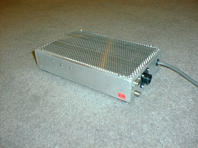
Receiver and Controller
This is the controller. The motor control and data cables run from here to the receiver and dish control motors. The RS-232 port connects to a local computer.
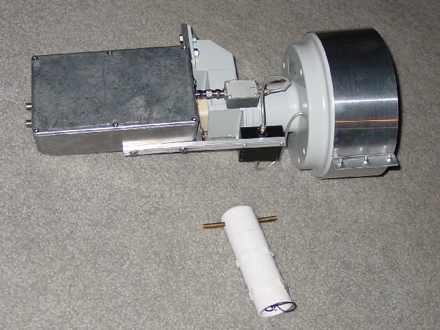
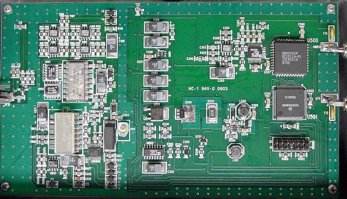
The receiver uses digital technology with a 8-bit analog to digital down converter (AD9283) digital downconverter GC1011A and Motorola 56F803 digital signal processor (DSP). The receiver and the low noise amplifier are mounted at the feed of the antenna. The receiver is controlled remotely using a STAMP microprocessor and RS-232 communications.
Also shown is the diode calibrator.
Radiometer Characteristics
| L.O. Frequency range | 1370-1800 MHz |
| L.O. Tuning steps | 40 kHz |
| L.O. Settle time | <5 ms |
| Rejection of LSB image | >20 dB |
| Bandwidth/Resolution Modes | 1200/8 kHz* |
| (Currently supported in ver 1.0 firmware) | 500/8 kHz |
| - | 250/4 kHz |
| - | 125/2 kHz |
| I.F. Center | 800 kHz |
| 6 dB I.F. range | 0.5-3 MHz |
| Preamp frequency range | 1400-1440 MHz |
| Typical system temperature | 150K |
| Typical L.O. leakage out of preamp | -105dBm |
| Preamp input for dB compression from out of band signals |
-24 dBm |
| Preamp input for intermodulation interference | -30 dBm |
| Control | RS-232 2400 baud |